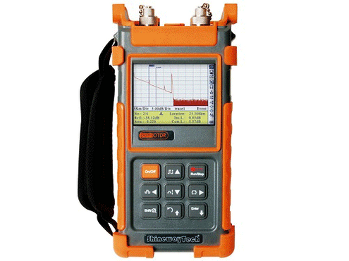
palmOTDR Series
|
|
 |
The most affordable compact high performance OTDR on the market today!
Once you've read about the palmOTDR below, why not click on the Vicom OTDR Selection Guide and find out which models are ideal for YOUR applications? |
||
 |
Comprehensive feature set - ideal for LAN/WAN/FTTx certification & trouble-shootingSinglemode: 1310/1490/1550, 1625/1650nm (with filter), up to 45dBMultimode: 850/1300nm, 21/24dB |
|
|
 |
The compact palmOTDR now offers even more testing capacities, flexibility and value with combination of 850/1300/1310/1490/1550/1625/1650nm (single/double/triple/quad wavelength) OTDR, 1310/1490/1550nm PON Power Meter, Stabilized Laser Source and VFL.
The OTDR wavelengths cover the applications of regular end-to-end fibre characterization (1310/1550nm), premise/enterprise LAN testing (850/1300nm), FTTx fibre link construction verification (1490nm) and PON live fibre troubleshooting (1625/1650nm with filter).
The integrated PON Power Meter can perform in-service testing of all PON signals (1310/1490/1550nm) on any spot of the network featuring pass-through design and burst mode support.
ShinewayTech's palmOTDR is your ultimate solution to meet various testing requirements of entire fibre network.
IN-SERVICE / LIVE FIBRE TESTING (1625/1650nm with filter)

LIVE OPTICAL SIGNAL CHECKWhen an OTDR tests using 1310, 1490 or 1550nm wavelength, the live signals transmitting in the tested fibre may not only affect OTDR measurements but also damage the equipment connected to the network (SDH/WDM/PON) and OTDR receiver. ShinewayTech's palmOTDR avoids the problem by starting an in-service communication check before testing - the message warning and auto termination functions effectively protecting test instruments and communications equipment. |
 |
BUILT-IN PON POWER METERThe integration of a PON Power Meter into such a small unit as the ShinewayTech palmOTDR greatly simplifies FTTx certification and troubleshooting and increases work efficiency. The PON Power Meter module can perform in-service testing of all PON signals (1310/1490/1550nm) on any spot of the network featuring pass-through design, burst mode and Pass/Warning/Fail assessment function, which can greatly help you evaluate PON signals' transmission quality. |
 |
|
 |
||
OPTIONAL STABILISED LASER SOURCE
The stabilized Laser Source shares the palmOTDR optical port and works on the same working wavelength as the palmOTDR.
OPTIONAL OPTICAL POWER METER
- No warm-up
- Absolute power value and power loss measurement
- High accuracy, zero shift
- Power monitoring, high-low limit setting
- Reference setting
 |
 |
OTDR TRACEMANAGER SOFTWARE
TraceManager software can display, analyze and edit trace files, generate and print comprehensive test and analysis reports in various forms
- Trace viewing, events analysiS
- Multi traces comparison
- Batch editing and flexible printing
- Bidirectional testing (Optional)
- CSV/ASCII report formats

MODELS IN THE SERIES |
Optical Options (for those applicable to each model variant, see below)
V=Visual Fault Locator/Visible Laser Diode; P=Optical Power Meter; S=Laser Source; I=Video Inspection Probe
| Model | Ports | Mode | Wavelength | Dynamic | Approx Distance |
| (Click for Details) | Range | (see note below) | |||
| (nm) | (dB) | (km) | |||
| palmOTDR-M20AE (V,P,S,I) | 1 | MM | 850/1300 | 21/24 | |
| palmOTDR-S20AE (V,P,S,I) | 1 | SM | 1310/1550 | 32/30 | 90-110 |
| palmOTDR-S20BE (V,P,S,I) | 1 | SM | 1310/1550 | 35/34 | 100-120 |
| palmOTDR-S20C/N (V,P,S,I) | 1 | SM | 1310/1550 | 40/38 | 110-130 |
| palmOTDR-S20D/N (V,P,S,I) | 1 | SM | 1310/1550 | 45/43 | 130-150 |
| palmOTDR-S20F (V,P,S,I) | 1 | SM | 1310/1550 | 50/48 | 140-160 |
| palmOTDR-S20C/P (V,P,S,I) | 1 | SM | 1310/1490/1550 | 38/37/37 | 110-130 |
| palmOTDR-S20C/X (V,P,S,I) | 1 | SM | 1310/1550 | 38/37 | 110-130 |
| 1 | SM | filtered 1625 or 1650 | 37 | 90-110 | |
| palmOTDR-P11C (V,S,I) | 1 | SM | filtered 1625 or 1650 | 37 | 90-110 |
| palmOTDR-P31C (S,I) | 1 | SM | 1310/1550 | 38/37 | 110-130 |
| 2 | SM | filtered 1625 or 1650 | 37 | 90-110 | |
| palmOTDR-Q40A (V,P,S,I) | 1 | SM | 1310/1550 | 32/30 | 90-110 |
| 2 | MM | 850/1300 | 21/24 | ||
NOTE: “Approx Distance” above refers to the approximate fibre distance that can accurately be certified based on 0.2dB/km fibre loss @ 1550nm (0.22dB for 1625/1650 only OTDRs) & 0.1dB splices every 2km. Note too that for the same distance, test times reduce with dynamic range increase – roughly half the test time for every 2-3dB increase in dynamic range.


